24 VDC Detect & Measure
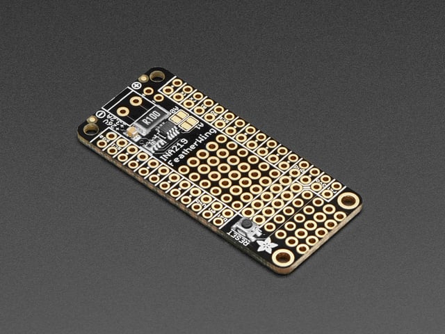
Measure and detect a nominal 24 VDC circuit with a 3.3V microcontroller. One side of a dual op-amp is used as a comparator to detect when a 24 VDC circuit is on or off. The other side of the op-amp is used as a voltage follower to measure the circuit voltage. The single connection to the 24 VDC circuit is high impedance so it does not interfere with it in any way. The circuit is built into a FeatherWing so it can be simply stacked on to a microcontroller for implementation.
The power for 24 VDC circuits can vary +/-10% or from 21.6 to 26.4 VDC. For most 3.3V microcontrollers, a voltage of < 0.8 VDC is considered LOW, and > 2.0 VDC is HIGH.
Functional Requirements
- Measure 0 to 27 VDC and output a proportional voltage of 0 to 3.3 VDC for analog input to a microcontroller.
- Detect when a 24 VDC circuit is on/live (> 21.6 VDC) and output > 2.0 VDC for digital input signal of HIGH. Detect when a 24 VDC circuit is off (not powered) and output < 0.8 VDC for digital input signal of LOW. The output should ideally be close to 3.3V for HIGH, and 0V when LOW.
- Use a single connection to the +V side and ground of the 24 VDC circuit
- The circuit monitored must not be influenced by the detection and measurement circuit.
The Circuit
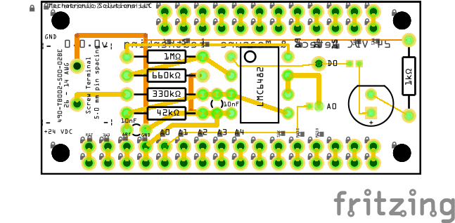
A dual op-amp LMC6482 is used and configured so that one op-amp is used as a voltage follower, and the second is used as a comparator.
The voltage input to the circuit is first reduced by a high impedance R3/R4 voltage divider, where the output from that is 3.3 V for an input of 27 V (13% above the nominal expected voltage of 24 VDC), or 2.7 V when the input is on the low size of the +/-10% tolarance or 21.6 V.
The output from the R3/R4 voltage divider is fed into the voltage follower op-amp (pins 5,6,7), where the gain is 1. The 0 to 3.3V input to pin #5 produces a proportional 0 to 3.3V output at pin #7 for analog input into a 3.3V microcontroller.
The output from the R3/R4 voltage divider is also fed into the comparator op-amp pin #3. When the voltage at pin #3 is greater than the voltage at pin #2, then the output at pin #1 will be HIGH (3.3 V from pin #8). When the voltage at pin #3 is less than the voltage at pin #2, then the output at pin #1 will be LOW (0 V from pin #4). The voltage at pin #2 is fixed at 2V by the R2/R1 voltage divider fed by the 3.3V at pin #8. When the input is 24 V, then the output from the R3/R4 voltage divider will be 3.0V, which is greater than the 2 V at pin #2, so the output from pin #1 will be HIGH (3.3V). See below the other possible results for various voltage inputs. Note that when the input voltage is 16 V or less, the voltage at pin #3 (1.9 V for 16 V input) will be lower than the voltage at pin #2 (2 V), causing the output at pin #1 to be LOW (0 V).
| Input [VDC] |
R3/R4 Voltage Divider Output [VDC] |
Pin #1 State |
|---|---|---|
| 26.4 | 3.3 | HIGH |
| 21.6 | 2.7 | HIGH |
| 16.0 | 1.9 | LOW |
An op-amp configured as a comparator always generates a voltage at the output pin (#1 for LMC6482) that is one of the following:
- When the voltage at the inverting input (pin #2) is greater than the voltage at the non-inverting input (pin #3), then the voltage at the V+ connection (pin #8)
- When the voltage at the inverting input (pin #2) is less than the voltage at the non-inverting input (pin #3), then the voltage at the V- connection (pin #4).
When using an op-amp, make sure to review the specifications agains the application. The following is relevent to the the Mfg PN LMC6482AIN/NOPB: The voltage at V+ must be within the supply voltage of 3 to 15.5 V.
Custom FeatherWing
The custom FeatherWing accepts 1x 24 VDC input and outputs a digital signal when the circuit is ON/OFF, and another analog output 0 to 3.3V for measurement of the circuit. Solder a jumper from Do to your digital input of choice. The LED for the digital output is optional (solder the pair of pads to enable). Solder the pair of pads at 'A0' to connect the analog output to A0, or run a small jumper to another analog input. &nsp;
Do you need help developing or customizing a IoT product for your needs? Send me an email requesting a free one hour phone / web share consultation.
The information presented on this website is for the author's use only. Use of this information by anyone other than the author is offered as guidelines and non-professional advice only. No liability is assumed by the author or this web site.




.jpg)










.png)


.png)


