Arduino Project
September 2021
Arduino Boat Anchor Light Timer
Functional Requirements
- Automatically turn on/off the boat's anchor light between sunset and sunrise. It is not necessary to be precise with the on/off timing, just so that the anchor light isn't on all day long, and definitely on when it is dark.
- Sunrise/sunset anchor light on timing must be accurate relative to the boat's cruising locations, from the USA east coast, and all the way down to the Florida Keys.
- The boat's anchor light switch will power the on/off device, and provide a manual means to activate/deactivate the device.
- When the boat's anchor light switch is turned on, blink the anchor light three times to confirm the timer is active.
Sunset / Sunrise
The boat's cruising locations are completely within the Eastern time zone. Eastern Daylight Time (EDT) is 4 hours behind Coordinated Universal Time (UTC) and occurs between mid March and early November of each year. Eastern Standard Time (EST) is 5 hours behind UTC beginning early November and ending mid March. June 20 to 22 is the longest day of the year north of the equator (summer solstice), and December 21/22 is the shortest day of the year (winter solstice).
Sunrise begins with the first sight of lightness in the morning, and is followed by civil dawn (sun 6 degrees below horizon), then nautical dawn (12 degrees), and then astronomical dawn (18 degrees). Similarly, sunset begins with civil dusk, then nautical dusk, and finally astronomical dusk. It is desirable to turn on the anchor light prior to civil dusk, and turn it off after astronomical dawn.
The most north east cruising location is at 39.220391,-76.457384 (Baltimore MD), and the most south west location is Key West FL at 24.554333,-81.788010. The boat could be in the Baltimore MD area year round, or it could be in the Chesapeake Bay (Baltimore MD) area June to November, and then the Key West FL area from November to June.
Sunset at Baltimore MD during summer solstice is at latest 8:35 pm, and sunrise is earliest at 5:39 am (EDT). Sunset at Baltimore MD during winter solstice is earliest at 4:45 pm (EST), and sunrise is latest at 7:25 am (EST). Sunset at Key West FL during summer solstice is earliest at 8:18 pm, and sunrise is earliest at 6:39 am (EDT). Sunset at Key West FL during the winter solstice is earliest at 5:43 pm (EST), and sunrise is earliest at 6:41 am. (EST) For this project, we are interested in the earliest sunset at 9:45 pm UTC, and the latest sunrise at 11:25 am UTC, both occuring at Baltimore MD during the winter solstice.
Timer Design
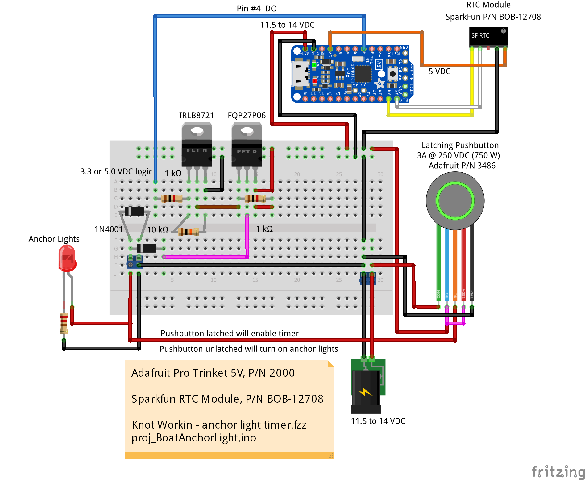
A real time clock (RTC) is the most simple and reliable way to determine when the earliest sunset at 9:45 pm UTC and the latest sunrise at 11:25 am UTC occur. A light sensor could be used, but that could be compromised by an obstruction, and it adds the complication of having one or more remote sensors. A small, simple microcontroller can interact with the RTC, and provide the necessary digital output. The anchor light needs to be switched on/off by either a relay, or a ground switching transistor such as a IRLB8721 power N-Channel MOSFET in a TO-220 package such as what is used in this FeatherWing.
Initially I chose an Adafruit Trinket 5V for the microcontroller, but I found it it didn't work well with the RTC (would not initialize). So I moved on to a Adafruit Pro Trinket 5V. It has 5V logic, supports I2C (for RTC), and plenty of I/O pins. The Trinket also has a voltage regulator that will accept 5.5V to 16VDC as input to the BAT+ and GND connections, and it has reverse polarity protection. The 5V output provides up to 150 mA of power. I/O pin A4 is for the RTC I2C SDA, and pin A5 is for the RTC I2C SCL connection. GPIO pin #4 was used for turning the anchor light on/off. Pin #13 is the built-in LED.
For the RTC, I used the SparkFun RTC Module with DS1307 chip, 5V logic, I2C communication (0x68), and CR1225 Lithium coin cell battery (good for 9 to 17 yrs). P/N BOB-12708
The anchor light requires switching of the 12V power (not the ground) in order to turn it on/off. I could use a relay, or a P-Channel MOSFET to do the switching. I wanted to work with a P-Channel MOSFET, so I went in that direction.
A P-Channel MOSFET has the source connected to the power rail (Vcc), and the gate is pulled to ground to allow current to flow, otherwise it is connected to Vcc through a pull-up resistor. I selected a FQP27P06 through hole TO-220-3 package P-Channel MOSFET for this project. In order to switch the P-Channel MOSFET gate, I used a IRLB8721 N-Channel MOSFET with it's gate connected to the Trinket digital output and through a 1k ohm resistor to manage the current required. I could have used an NPN bipolar junction transistor for the gate control, but I wanted to develop something that could be used on other projects with a wide range of voltage and current requirements.
The P Channel MOSFET provides a path to Vcc for the switched load. When the N Channel MOSFET gate is high, it pulls down the P Channel MOSFET to gate, creating a path for the load to Vcc via the P Channel MOSFET drain. When the N Channel MOSFET gate is low, the P Channel MOSFET gate is pulled to Vcc by R2, preventing the P Channel MOSFET drain from conducting to Vcc. R1 limits the current (for microcontroller DO). R2 pulls the P Channel MOSFET gate high when the N Channel MOSFET is off. Less than 2 mA demand on the digital input.
/*
  Adafruit Pro Trinket 5V
    P/N 2000
    https://www.adafruit.com/product/2000


  SparkFun RTC Module with DS1307 chip
    P/N BOB-12708
    https://www.sparkfun.com/products/12708
    I2C 0x68

  NOTE:  When the Trinket is powered, it will go into
         bootloader mode for 10 seconds and blink the
         built in LED.
 */

// Adafruit Pro Trinket 5V
//  In Arduino IDE, select 'Tools','Board','Adafruit Boards','Adafruit Pro Trinket 5V/16MHz (USB).'
//  Change 'Programmer' from 'AVRISP mkll' to 'USBtinyISP'.
//  Port:  <no USB port is visible or can be chosen>

// IMPORTANT:
//  To upload a sketch, press & release the reset button on the
//  Trinket, then in the Arduino IDE click 'Upload'.


/////////////////////////////////////////////////////////////////////////
// Built in LED(s)
// #13 ESP32, STM32F2, Teensy, 32u4, 382P, M0, M4, Uno
//  #1 Trinket
const byte pinBuiltInLED = 13;

const byte pinAnchorLight = 4;


void blinkLED(byte ledPIN){
  //  consumes 300 ms.
  for(int i = 5; i>0; i--){
    digitalWrite(ledPIN, HIGH);
    delay(30);
    digitalWrite(ledPIN, LOW);
    delay(30);
  }
} //blinkLED()


void blinkERR(byte ledPIN){
  // S-O-S
  const int S = 150, O = 300;
  for(int i = 3; i>0; i--){
    digitalWrite(ledPIN, HIGH);
    delay(S);
    digitalWrite(ledPIN, LOW);
    delay(S);
  }
  delay(200);
  for(int i = 3; i>0; i--){
    digitalWrite(ledPIN, HIGH);
    delay(O);
    digitalWrite(ledPIN, LOW);
    delay(O);
  }
  delay(200);
  for(int i = 3; i>0; i--){
    digitalWrite(ledPIN, HIGH);
    delay(S);
    digitalWrite(ledPIN, LOW);
    delay(S);
  }
  delay(200);
} // blinkERR()


/////////////////////////////////////////////////////////////////////////
//  RTC hardware is DS1307
//  Library: "RTClib" by Adafruit (a fork of JeeLab's RTC library)
//    "RTClib.h" supports DS3231, PCF8523, and DS1307 RTC
//  https://github.com/adafruit/RTClib

#include "RTClib.h"
RTC_DS1307 rtc;
//NOTE:  The RTC date/time is set to UTC

struct TIME_STRUCT_24H{
  byte hour;
  byte minute;
};
TIME_STRUCT_24H sunriseUTC = {11, 25};  // 11:25 am UTC (-4 hrs = 7:25 am EDT)
TIME_STRUCT_24H sunsetUTC = {21, 45};   // 21:45 or 9:45 pm UTC

//////////////////////////////////////////////////////////////////////////////
// TimerA
const unsigned long timerIntervalA = 5000;  // 5 sec
unsigned long timerAlap = millis();  // timer

void timerA() {
  //  Timer A
  if (timerAlap > millis())  timerAlap = millis();
  if (millis() - timerAlap > timerIntervalA) {
    DateTime now = rtc.now();

    if (now.hour()  > sunsetUTC.hour) {
      // Now after sunset (21:45)
      digitalWrite(pinBuiltInLED, HIGH);
      digitalWrite(pinAnchorLight, HIGH);
    } else if (now.hour() == sunsetUTC.hour && now.minute() > sunsetUTC.minute) {
      // Now @ sunset hour and > sunset minute (21:45 UTC)
      digitalWrite(pinBuiltInLED, HIGH);
      digitalWrite(pinAnchorLight, HIGH);
    } else if (now.hour()  < sunriseUTC.hour) {
      // Now before sunrise (11:25 UTC)
      digitalWrite(pinBuiltInLED, HIGH);
      digitalWrite(pinAnchorLight, HIGH);
    } else if (now.hour()  == sunriseUTC.hour && now.minute() < sunriseUTC.minute) {
      // Now @ sunrise hour and < sunrise minute (11:25 UTC)
      digitalWrite(pinBuiltInLED, HIGH);
      digitalWrite(pinAnchorLight, HIGH);
    } else {
      digitalWrite(pinBuiltInLED, LOW);
      digitalWrite(pinAnchorLight, LOW);
    }

    // 13:27 vs 11:25 & 21:45

    timerAlap = millis(); // reset the timer
  }
} // timerA()


void setup() {

  pinMode(pinBuiltInLED, OUTPUT);
  digitalWrite(pinBuiltInLED, LOW);

  pinMode(pinAnchorLight, OUTPUT);
  digitalWrite(pinAnchorLight, HIGH);

  digitalWrite(pinBuiltInLED, HIGH);
  if (! rtc.begin()) {
    while (1) {
      blinkERR(pinBuiltInLED);
      delay(2000);
    }
  }
  digitalWrite(pinBuiltInLED, LOW);

  if (! rtc.isrunning()) {
    while (1) {
      blinkERR(pinBuiltInLED);
      delay(2000);
    }
    // When time needs to be set on a new device, or after a power loss, the
    // following line sets the RTC to the date & time this sketch was compiled
    //rtc.adjust(DateTime(F(__DATE__), F(__TIME__)));
    // This line sets the RTC with an explicit date & time, for example to set
    // January 21, 2014 at 3am you would call:
    // rtc.adjust(DateTime(2014, 1, 21, 3, 0, 0));
  }
  // Specifically set the time in UTC..
  //rtc.adjust(DateTime(2021, 9, 6, 14, 22, 0));

  // Turn the anchor light on/off three times to indicate the timer is active.
  digitalWrite(pinBuiltInLED, HIGH);
  digitalWrite(pinAnchorLight, HIGH);
  delay(1000);
  digitalWrite(pinBuiltInLED, LOW);
  digitalWrite(pinAnchorLight, LOW);
  delay(1000);
  digitalWrite(pinBuiltInLED, HIGH);
  digitalWrite(pinAnchorLight, HIGH);
  delay(1000);
  digitalWrite(pinBuiltInLED, LOW);
  digitalWrite(pinAnchorLight, LOW);
  delay(1000);
  digitalWrite(pinBuiltInLED, HIGH);
  digitalWrite(pinAnchorLight, HIGH);
  delay(1000);
  digitalWrite(pinBuiltInLED, LOW);
  digitalWrite(pinAnchorLight, LOW);

  timerAlap = millis() + timerIntervalA; // initialize the timer
} // setup()


void loop() {

  timerA();

} // loop()
Do you need help developing or customizing a IoT product for your needs? Send me an email requesting a free one hour phone / web share consultation.
The information presented on this website is for the author's use only. Use of this information by anyone other than the author is offered as guidelines and non-professional advice only. No liability is assumed by the author or this web site.


.png)
.png)
.png)
.png)
.png)
.png)


