M4 Express SAMD51 Cortex M4
Introduction
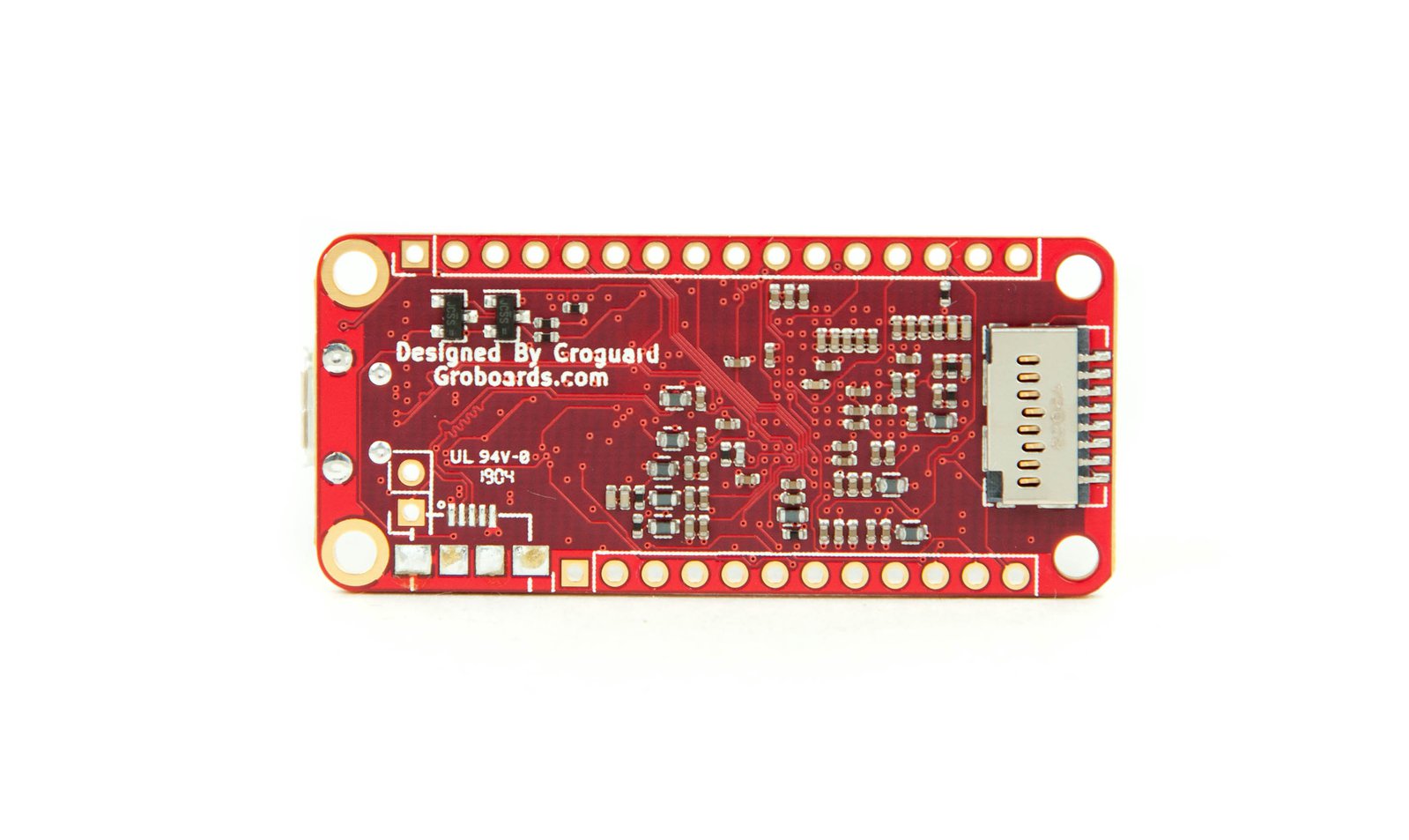
120MHz Cortex M4 (ATSAMD51J19 chip). 512KB Flash and 192KB RAM. 2 MB SPI FLASH No EEPROM. 3.3V @ 500 mA peak regulator. Mini NeoPixel.
Hardware
Note: Express refers to the inclusion of an extra 2MB flash chip on the board that provides you with extra space for CircuitPython. The The QSPI Flash is very fast!
A0 & A1 are analog input and true analog output , 0 to 3.3V.
A2, A3, A4, A5 support analog input and digital I/O + PWM.
Pull the RST pin to ground to manually reset the ATSAMD51.
#13 is the built-in red LED.
#8 is the built-in NeoPixel
A6 / pin #20 is connected to the BAT pin where a double 100 k resistor divider resides.
Pin #6 can be used for interrupts via attachInterrupt(). forum post
6 x hardware SERCOMS: SPI, I2C and Serial. Serial1 is on pins #0 (Rx) and #1 (Tx). I2C SDA on pin #21 and SCL on pin #22. Hardware SPI on #25 / SCK, #24 MOSI, #23 MISO. You can use the above SERCOMS for anything, above is just the default configuration. HOw to create another SPI How to create a new hardware serial Make a new I2C SERCOM See also: Using ATSAMD21 SERCOM for more SPI, I2C and Serial ports Pins for up to five additional I2C buses: A2(SDA) & A3 (SCL), A4 (SDA) & A1 (SCL), #12 (SDA) & #13 (SCL), TX (SDA) & RX (SCL), #5 (SDA) & SCK (SCL).
First choice for DIO, including PWM output is pins #4, #5, #6, #9, (reserve #10, #11, and #12 for SERCOMS).
Special Code Considerations
WARNING: typecasting variables can be troublesome in certain cases.
Functions That Work
atoi(), sprintf(),
iota() convert an integer to a char array.
byte arrData[16];
int n = random(0,255);
itoa(n, (char*)arrData, 10);
dtostrf()
Not available for M0 or M4. See solution below.
/////////////////////////////////////////////////////////////////////////

/*
  dtostrf - Emulation for dtostrf function from avr-libc
  Copyright (c) 2015 Arduino LLC.  All rights reserved.
  This library is free software; you can redistribute it and/or
  modify it under the terms of the GNU Lesser General Public
  License as published by the Free Software Foundation; either
  version 2.1 of the License, or (at your option) any later version.
  This library is distributed in the hope that it will be useful,
  but WITHOUT ANY WARRANTY; without even the implied warranty of
  MERCHANTABILITY or FITNESS FOR A PARTICULAR PURPOSE.  See the GNU
  Lesser General Public License for more details.
  You should have received a copy of the GNU Lesser General Public
  License along with this library; if not, write to the Free Software
  Foundation, Inc., 51 Franklin St, Fifth Floor, Boston, MA  02110-1301  USA
*/
// https://github.com/arduino/ArduinoCore-samd/blob/master/cores/arduino/avr/dtostrf.c

/*
char buff[14];
float f = -3.1415926;
Serial.print("f = ");Serial.println(f, 6);
sprintf(buff, "%E", f);
Serial.print("buff = '"); Serial.print(buff); Serial.println("'");
*/

char *dtostrf (double val, signed char width, unsigned char prec, char *sout) {
  asm(".global _printf_float");
  char fmt[20];
  sprintf(fmt, "%%%d.%df", width, prec);
  sprintf(sout, fmt, val);
  return sout;
} // dtostrf()
/////////////////////////////////////////////////////////////////////////
Firmware
Serial goes to USB when using the Adafruit M0/M4 Core. Serial vs SerialUSB
/*
  AF_Feather_M4_Express_SAMD51_template.ino

  Adafruit Feather M4 Express SAMD51


  In Arduino IDE, set board to 'Adafruit Feather M4 Express (SAMD51)'

  If bootloading frozen, click RST button twice quickly.

  The red LED will pulse and the RGB LED will be green when you are
  in bootloader mode.

  NeoPixel = green if OK, RED on USB failure.

  The yellow “charging” LED flickers constantly whenever the Feather is powered by USB

  Arduino C++ code or CircuitPython


  WARNING:  The Arduino IDE serial monitor causes setup() to wait until
  the serial monitor IDE is run.

*/

/////////////////////////////////////////////////////////////////////////
// Built in LED(s)

const uint8_t pinBuiltInLED = 13;

/////////////////////////////////////////////////////////////////////////
// blinkLEDnoDelay()
unsigned long LEDblinkPeriod = 8;
unsigned long LEDblinkLast = 0;
uint8_t LEDblinkPWM = 0;
bool LEDblinkState = false;
uint8_t LEDlastMode = 0;

void blinkLEDnoDelay(byte pin, byte mode) {
  // Blink the LED on 'pin' without using delay() according to
  // the 'mode' argument defined below.
  // pin must support PWM.
  //
  // mode:
  //  0 = breathing
  //  1 = blink slow constantly
  //  2 = blink fast constantly
  //  3 = slow burst every 1 second
  //  4 = fast burst every 1 second
  //
  // Required global variables: LEDblinkPeriod, LEDblinkLast, LEDblinkPWM, LEDblinkState, LEDlastMode
  if (mode == 0) {
    // breathing
    LEDblinkPeriod = 8;
    if (LEDlastMode != mode) {
      LEDblinkPWM = 0;
      LEDblinkState = true;
      digitalWrite(pin, LOW);
    }
    if (millis() - LEDblinkLast >= LEDblinkPeriod) {
        if (LEDblinkPWM > 254) LEDblinkState = false;
        if (LEDblinkPWM < 1) LEDblinkState = true;
        if (LEDblinkState) {
            LEDblinkPWM++;
        } else {
            LEDblinkPWM--;
        }
        analogWrite(pin, LEDblinkPWM);
        LEDlastMode = mode;
        LEDblinkLast = millis();
    }
  } else if (mode == 1) {
    // blink slow constantly
    LEDblinkPeriod = 1000;
    if (millis() - LEDblinkLast >= LEDblinkPeriod) {
        digitalWrite(pin, LEDblinkState);
        LEDblinkState = !LEDblinkState;
        LEDlastMode = mode;
        LEDblinkLast = millis();
    }
  } else if (mode == 2) {
    // blink fast constantly
    LEDblinkPeriod = 100;
    if (millis() - LEDblinkLast >= LEDblinkPeriod) {
        digitalWrite(pin, LEDblinkState);
        LEDblinkState = !LEDblinkState;
        LEDlastMode = mode;
        LEDblinkLast = millis();
    }
  } else if (mode == 3) {
    // slow burst every 1 second
    // Slow 4 blinks (lazy burst) followed by 1 sec pause
    if (LEDlastMode != mode) {
      LEDblinkPWM = 0;
      LEDblinkState = true;
      LEDblinkPeriod = 100;
    }
    if (millis() - LEDblinkLast >= LEDblinkPeriod) {
        if (LEDblinkPWM < 7) {
          if (LEDblinkPWM == 0) LEDblinkState = true;
          digitalWrite(pin, LEDblinkState);
          LEDblinkPeriod = 100;
          LEDblinkState = !LEDblinkState;
          LEDblinkPWM++;
        } else {
          digitalWrite(pin, LOW);
          LEDblinkPWM = 0;
          LEDblinkPeriod = 1000;
        }
        LEDlastMode = mode;
        LEDblinkLast = millis();
    }
  } else if (mode == 4) {
    // fast burst every 1 second
    // Fast 4 blinks (burst) followed by 1 sec pause
    if (LEDlastMode != mode) {
      LEDblinkPWM = 0;
      LEDblinkState = true;
      LEDblinkPeriod = 25;
    }
    if (millis() - LEDblinkLast >= LEDblinkPeriod) {
        if (LEDblinkPWM < 7) {
          if (LEDblinkPWM == 0) LEDblinkState = true;
          digitalWrite(pin, LEDblinkState);
          LEDblinkPeriod = 25;
          LEDblinkState = !LEDblinkState;
          LEDblinkPWM++;
        } else {
          digitalWrite(pin, LOW);
          LEDblinkPWM = 0;
          LEDblinkPeriod = 1000;
        }
        LEDlastMode = mode;
        LEDblinkLast = millis();
    }
  } // mode
}   // blinkLEDnoDelay()


/////////////////////////////////////////////////////////////////////////
// Built-in NeoPixel (RGB LED)
//
// set it up as a single-LED strand on pin 8

const uint8_t pinBuiltInNeoPixel = 8;

#include <Adafruit_NeoPixel.h>
#define NUMPIXELS  1
Adafruit_NeoPixel pixels = Adafruit_NeoPixel(NUMPIXELS, pinBuiltInNeoPixel, NEO_GRB + NEO_KHZ800);
// Argument 1 = Number of pixels in NeoPixel strip
// Argument 2 = Arduino pin number (most are valid)
// Argument 3 = Pixel type flags, add together as needed:
//   NEO_KHZ800  800 KHz bitstream (most NeoPixel products w/WS2812 LEDs)
//   NEO_GRB     Pixels are wired for GRB bitstream (most NeoPixel products)

const unsigned long neoPixelTimerInterval = 500;
unsigned long neoPixelTimerLap = millis();  // timer

void neoPixelRainbow() {
  uint16_t i, j;
  uint8_t maxBright = 4;

  for(j=0; j<256; j++) {
    for(i=0; i<pixels.numPixels(); i++) {
      pixels.setPixelColor(i, WheelDim((i+j) & 255, maxBright));
    }
    if (neoPixelTimerLap > millis())  neoPixelTimerLap = millis();
    if (millis() - neoPixelTimerLap > neoPixelTimerInterval) {
      neoPixelTimerLap = millis(); // reset the timer
      pixels.show();
    }
  }
} // neoPixelRainbow()

// A version of Wheel that dims pixels down for photos/video
// maxBright is from 0 to 255; low numbers are dimmer.
// NeoPixel brightness is nonlinear, so play with the maxBright number. I used 4 for recent video.
uint32_t WheelDim(byte WheelPos, uint8_t maxBright){
  WheelPos = 255 - WheelPos;
  uint16_t r = 0, g = 0, b = 0;

  if(WheelPos < 85) {
    r = 255 - WheelPos * 3;
    b = WheelPos * 3;
  } else if(WheelPos < 170) {
    WheelPos -= 85;
    g = WheelPos * 3;
    b = 255 - WheelPos * 3;
  } else {
    WheelPos -= 170;
    r = WheelPos * 3;
    g = 255 - WheelPos * 3;
  }

  r = r * maxBright / 255;
  g = g * maxBright / 255;
  b = b * maxBright / 255;

  return pixels.Color(r, g, b);
}


/////////////////////////////////////////////////////////////////////////
//  Built-in 2 MB QSPI (Quad SPI) Flash chip
//  (acts as storage that you can read/write files to)

// Connected to 6 pins not brought out to GPIO pads
// QSPI allows 4 data in/out lines.
// Arduino library:  https://github.com/adafruit/Adafruit_SPIFlash
//  See examples 'Adafruit SPIFlash'
//  Full QSPI/SPI support with SdFat as the FAT filesystem manager
//
// Write speed : 546.99 KB/s.
// Read speed : 5698.78 KB/s.

#include "SdFat.h"
#include "Adafruit_SPIFlash.h"

// Uncomment to run example with custom SPI and SS e.g with FRAM breakout
// #define CUSTOM_CS   A5
// #define CUSTOM_SPI  SPI

#if defined(CUSTOM_CS) && defined(CUSTOM_SPI)
  Adafruit_FlashTransport_SPI flashTransport(CUSTOM_CS, CUSTOM_SPI);

#elif defined(ARDUINO_ARCH_ESP32)
  // ESP32 use same flash device that store code.
  // Therefore there is no need to specify the SPI and SS
  Adafruit_FlashTransport_ESP32 flashTransport;

#else
  // On-board external flash (QSPI or SPI) macros should already
  // defined in your board variant if supported
  // - EXTERNAL_FLASH_USE_QSPI
  // - EXTERNAL_FLASH_USE_CS/EXTERNAL_FLASH_USE_SPI
  #if defined(EXTERNAL_FLASH_USE_QSPI)
    Adafruit_FlashTransport_QSPI flashTransport;

  #elif defined(EXTERNAL_FLASH_USE_SPI)
    Adafruit_FlashTransport_SPI flashTransport(EXTERNAL_FLASH_USE_CS, EXTERNAL_FLASH_USE_SPI);

  #else
    #error No QSPI/SPI flash are defined on your board variant.h !
  #endif
#endif

Adafruit_SPIFlash flash(&flashTransport);

/////////////////////////////////////////////////////////////////////////


void setup() {

  // For ATSAMD21 and ATSAMD51:
  //  ARef pin, use analogReference(AR_EXTERNAL)
  //  Pin with pullup:
  //    Use: pinMode(pin, INPUT_PULLUP)
  //    NOT: pinMode(pin, INPUT)
  //         digitalWrite(pin, HIGH)

  Serial.begin(115200);
  while (!Serial) {
    delay(1);
  }
  Serial.println("\nSerial ready");

  pinMode(pinBuiltInLED, OUTPUT);
  digitalWrite(pinBuiltInLED, LOW);

  // Initialize the built-in NeoPixel (initially set to green)
  pixels.begin();
  pixels.show();

  // NeoPixel color test
  //delay(5000);
  // .setPixelColor(n, red, green, blue, white);
  //pixels.setPixelColor(0, 255, 0, 0, 4);  // red
  //pixels.show();
  //delay(5000);
  //
  //pixels.setPixelColor(0, 0, 255, 0, 4);  // green
  //pixels.show();
  //delay(5000);

  //pixels.setPixelColor(0, 0, 0, 255, 4);  // blue
  //pixels.show();
  //delay(5000);
  //
  //pixels.setPixelColor(0, 255, 255, 255, 4);  // white
  //pixels.show();
  //delay(5000);
  //
  //pixels.setPixelColor(0, 0, 0, 0, 4);  // black
  //pixels.show();

  // 2 MB QSPI (Quad SPI) Flash chip
  Serial.println("\n2 MB QSPI (Quad SPI) Flash chip");
  flash.begin();
  Serial.print("JEDEC ID: 0x"); Serial.println(flash.getJEDECID(), HEX);
  Serial.print("Flash size: "); Serial.print(flash.size() / 1024); Serial.println(" KB");
  // WARNING:  Must format to use as SD drive (see examples Adafruit SPIFlash -> SdFat_format)
  //           Formatting will erase CircuitPython!

  Serial.println("\nSetup complete\n");
} // setup()


void loop() {

  blinkLEDnoDelay(pinBuiltInLED, 0);

  neoPixelRainbow();

} // loop()
Do you need help developing or customizing a IoT product for your needs? Send me an email requesting a free one hour phone / web share consultation.
The information presented on this website is for the author's use only. Use of this information by anyone other than the author is offered as guidelines and non-professional advice only. No liability is assumed by the author or this web site.
.png)


.png)


