XBee I/O Line Passing
I/O Line Passing is a configuration of XBees where the digital/analog I/O are virtually linked between XBee modules. XBees may be configured for I/O Line Passing using either a Periodic Sampling or Change Detect method (my terminology). Periodic Sampling uses the feature of IR to periodically send out packets with data about the Sender analog/digital input status. Change Detect uses the feature of IC to only send out packets with data about the Sender I/O status when an input has changed. In either case, the Receiver needs the IA parameter configured to read those packets and respond by updating it's outputs.
Applications for I/O Line Passing are diverse, given that you only need to use 3.3V logic for the digital input of the transmitting XBee, and then one or more XBees can receive and respond locally to that change. However, analog input / PWM output transmission is coarse, and if you need accurate analog data transmission, then the application is then best served by using a microcontroller connected to the UART of each XBee, with decoding of the packet data itself.
This page provides carefully engineered examples to demonstrate how to configure XBees for either Periodic Sampling or Change Detect I/O Line Passing. Note that both methods may be implemented together, and that although the examples demonstrate a unidirectional relationship between the XBees (for clarity), a bidirectional arrangement is also possible. Two digital outputs are configured in the examples, but analog output could also be implemented for pairs AD0(pin 20) / PWM0(pin 6) and AD1(pin 19) / PWM1(pin 7).
The XBee 802.15.4 operate at 2.4 GHz but are not compatible with the ZNet/ZB/"series 2" modules. See SparkFun XBee buying guide
Static Configuration Settings
The configuration settings below are unique to my example, and constant throughout this reference. Your actual addresses will probably vary, but the mapping of MY to DL should be similar. Note that all hexadecimal values are prefeced by "0x" for clarity, but in the XCTU application you enter them as hexadecimal, but do not preface them with "0x".
| Sender | Receiver | |
|---|---|---|
| CH | 0xC | 0xC |
| PAN ID | 0x3334 | 0x3334 |
| DH Destination High | 0x0000 | 0x0000 |
| DL Destination Low | 0x4141 | 0x1818 |
| MY Address | 0x1818 | 0x4141 |
| CE Coordinator Enable | 0x1 (coordinator) |
0x0 (EndUser) |
| AP Mode (1) | AP=0x0 | AP=0x0 |
(1) AP Mode may be transparent (0x0), or API (0x1), but should be the same for all XBees
Configuration Settings Relevent to I/O Passing
IC Change Detect:
IC=0x0 disables input detection.
IC=0xFF transmits a packet when any digital input D0..D7 changes.
IC=[bit mask of DIO lines] specifies DIO to monitor. Ex. IC=0xC will monitor only DI2 & DI3.
IR Sample Rate:
IR=0x0 sampling disabled
IR>0x0 defines the sample rate for analog/digital inputs.
Packets will be sent from the XBee with information about the status/value of the
analog/digital inputs (for those enabled as such) at the sample rate specified
by IR.
Note that XBees in transparent mode (AP=0) discard the I/O data packets they receive.
Recommend IR=0x64 (0x64 = 100 * 1 ms = 100 ms = 10 samples/sec = 10 Hz).
IA I/O Input Address:
IA=0xFF will prevent received I/O packets from changing outputs.
IA=0xFFFF will allow any received I/O packet to change outputs.
IA=[MY address] will only accept inputs from this specified address
IU I/O Output Enable:
IU=0x1 enables sending of I/O data out UART using an API frame (regardless of AP mode) at the sample rate specified by IR.
IU=0x0 disables sending of I/O data out UART using an API frame, and also causes received line state packets to update the local output pins.
Note that IU is NOT required for I/O Line passing, and it may be optional disabled.
AP API Enable Value does not affect I/O line passing. AP = 0x0 (transparent mode) OR 0x1 (API Mode)
Digital inputs will recognize a voltage lower than 1.0V as low, or greater than 2.3V as high.
DO max source is 2 mA per pin.
Connect Vref to 3.3 VDC regulated.
The XBee has 8 usable DIO lines that can be used to send digital data (DIO0 .. DIO7).
Periodic Sampling Configuration
The Sender periodically samples enabled digital inputs (IR=0x64 = 10 Hz) and sends out packets over the network. Changes to the Sender's inputs do NOT trigger a packet transmit (IC=0x0). When the Receiver receives a packet, (DL=0x4141), it's digital outputs are updated to match the sender because it's I/O Output Enable setting is disabled (IU=0), and the IA I/O Input Address is set to allow any received I/O packet to change outputs (IA=0xFFFF). Note that if the Sender XBee stops sending packets (because it's power is lost), then the Receiver XBee will stop asserting the output for DO3 after 25.5 seconds.
| Sender | Receiver | |
|---|---|---|
| DH Destination High | 0x0000 | 0x0000 |
| DL Destination Low | 0x4141 | 0x1818 |
| MY Address | 0x1818 | 0x4141 |
| DIO 3 (pin 17) | DI3 | DO3 LOW |
| DIO 4 (pin 18) | DI2 | DO2 LOW |
| IR Sample Rate | IR=0x64 (1) | IR=0x0 (disable) |
| IC DIO Change Detect | IC=0x0 (disable) | IC=0x0 (disable) |
| IA I/O Input Address | IA=0xFF (disable) | IA=0x1818 (2) |
| IU I/O Output Enable | IU=0x0 (disable) | IU=0x0 (disable) |
| T2 D2 Output Timeout | 0x0 (disabled) | |
| T3 D3 Output Timeout | 0xFF (3) |
Notes:
(1) IR=0x64 = 100 DEC. 100 * 1 ms = 100 ms = 10 samples/sec = 10 Hz
(2) IA=0xFFFF will accept packet from any XBee. IA=0x1818 forces XBee to only change I/O in response to packets from XBee with MY=0x1818
(3) 0xFF = 255 * 100 ms = 25500 ms = 25.5 sec
The following may optionally be disabled for the Sender & Receiver: IC=0x0.
Change Detect Configuration
The Sender is configured so that it does not periodically sample (IR=0x0), instead it monitors D2 & D3 (IC=0xC) and when it detects a change on a pin, it generates a sample and sends it to the receiver (DL=0x4141) over the the network. When the Receiver receives a sample packet from the Sender, the digital outputs on the Receiver are updated to match the sender because the I/O Output Enable setting is disabled (IU=0), and the I/O Input Address is set to only allow received I/O packets from MY=0x1818 to change outputs (IA=0x1818). Note that if no packet is sent from the Sender to the Receiver for a digital I/O (Sender XBee powered off), then the Receiver will change the output back to the default state (DO3 LOW) after the T3 timeout of 25.5 seconds (T3=0xFF). The Receiver digital I/O D3 will not timeout when no new packet is received because T2=0x0 (timer disables). See important Note #1 below table about IC=0xFF and consider how this would affect the digital I/O timeout behaviour.
| Sender | Receiver | |
|---|---|---|
| DH Destination High | 0x0000 | 0x0000 |
| DL Destination Low | 0x4141 | 0x1818 |
| MY Address | 0x1818 | 0x4141 |
| DIO 3 (pin 17) | DI3 | DO3 LOW |
| DIO 4 (pin 18) | DI2 | DO2 LOW |
| IR Sample Rate | IR=0x0 (disable) | IR=0x0 (disable) |
| IC DIO Change Detect | IC=0xC (1) | IC=0x0 (disable) |
| IA I/O Input Address | IA=0xFF (disable) | IA=0x1818 (2) |
| IU I/O Output Enable | IU=0x0 (disable) | IU=0x0 (disable) |
| T2 D2 Output Timeout | 0x0 (disabled) | |
| T3 D3 Output Timeout | 0xFF (3) |
Notes:
(1) IC=0xC is a bit mask that forces the XBee to transmit a packet only when DI2 or DI3 change. WARNING: If IC=0xFF then any changee in input from DI0..DI7 will cause a packet to be transmitted - including activity from DI7 (CTS flow control), DI5 (Associated indicator) if they are enabled as such.
(2) IA=0xFFFF will accept packet from any XBee. IA=0x1818 forces XBee to only change I/O in response to packets from XBee with MY=0x1818
(3) 0xFF = 255 * 100 ms = 25500 ms = 25.5 sec
The following may optionally be disabled for the Sender & Receiver: IC=0x0.

Helpful Links
Do you need help developing or customizing a IoT product for your needs? Send me an email requesting a free one hour phone / web share consultation.
The information presented on this website is for the author's use only. Use of this information by anyone other than the author is offered as guidelines and non-professional advice only. No liability is assumed by the author or this web site.
Sensors

Sensor Calibration
Sensitivity, Resolution, Response Time, etc.

50000 PPM (5%) CO2 Sensors

MQ Gas Sensors

MQ-6 LPG Gas Sensor

MQ-7 Carbon Monoxide Gas Sensor
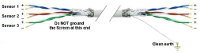
Sensor to microcontroller / data acquisition device cables

Accelerometers
IMU / Gyroscope
Magnetometer
Audio
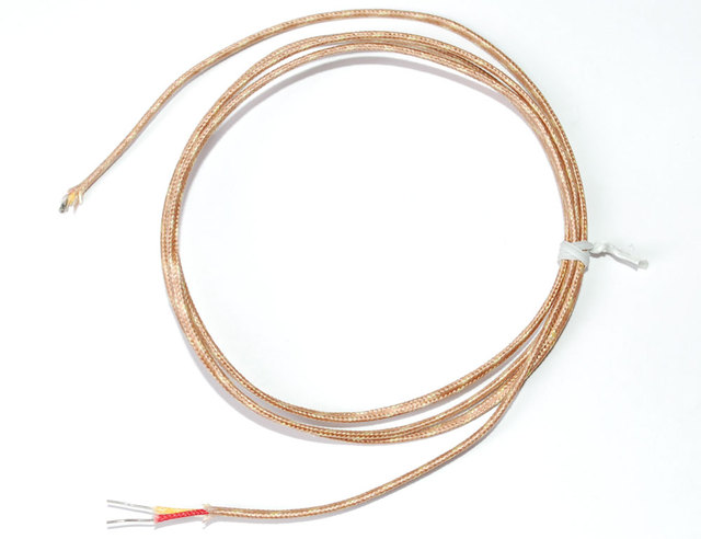
Thermocouple
AF Sensirion SHT40 Temperature & Humidity Sensor
.svg)
Motion Sensors
.png "object detection sensors")
Object Detection Sensors

Strain Gauge

Color
.png)
Pressure
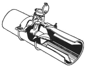
Liquid Flow Meter

Operational Amplifiers
Components

Tools
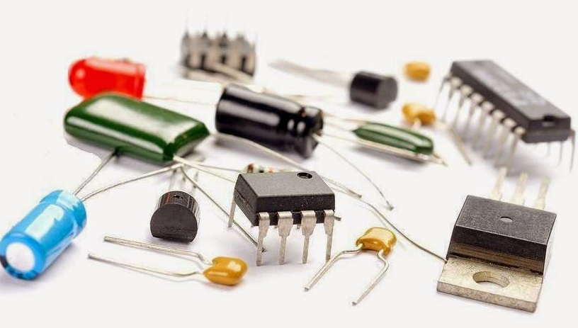
Basic Components

Suppliers

VAC

XBee I/O Line Passing
xBee wireless communication modules + Arduino
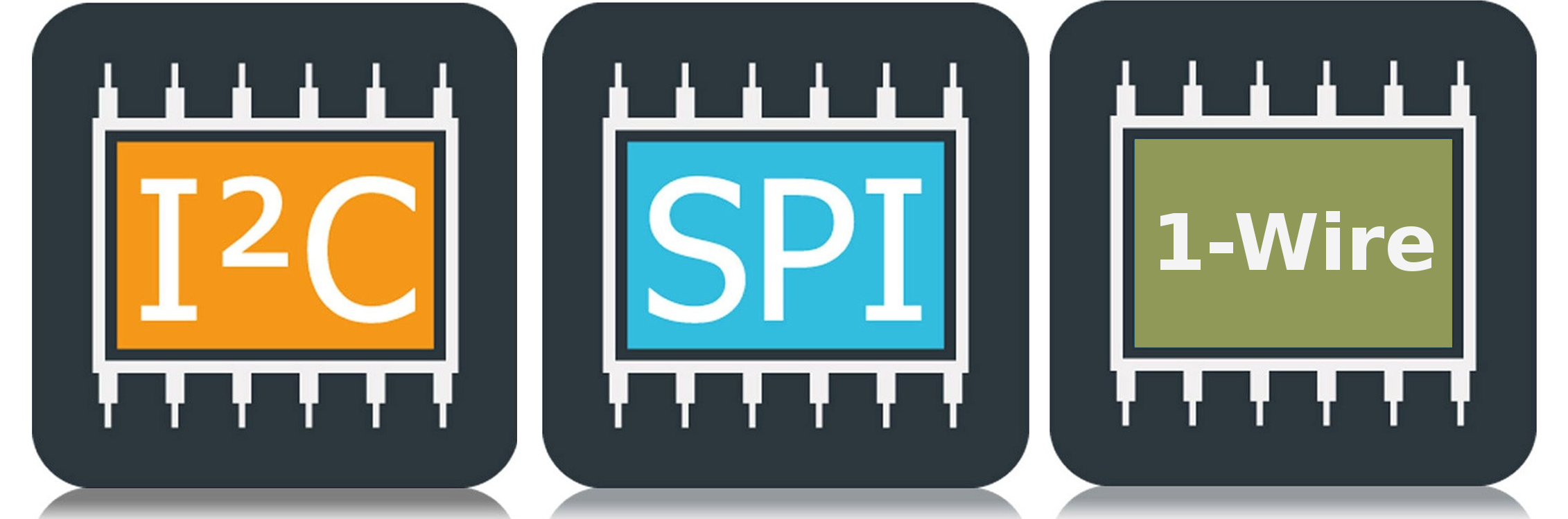
I2C bus / SPI / 1-Wire
.png)
UART TTL Serial RS-232
.png)
LoRa Communications

Triac
Light Emitting Diode (LED)

NeoPixels
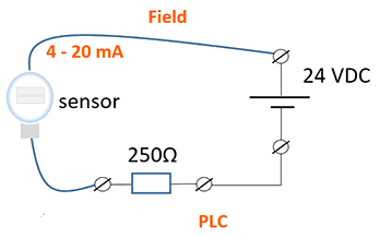
4-20 mA Current Loops
.png)
Human Health & Electrical Power
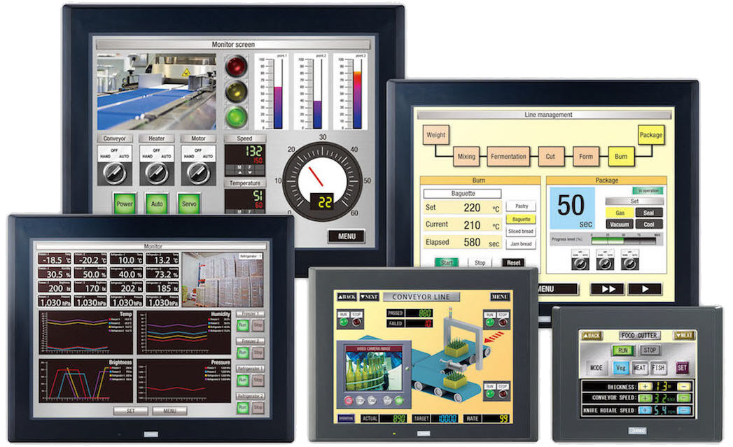
HMI
")
Mobile Apps
Hall Effect Sensor
NTC Thermistor
.png "Op Amp - operational amplifier. Amplify, filter, add, manipulate analog signals.")
Amplify an Analog Signal

Offset a input signal
.png)
Electric Motors
.jpg)
Laptop 12V Power Supply

MCP2515 CAN Bus Module
.png)
TJA1050 CAN Bus Module

1.2" 4-Digit 7-Segment LED Display

Batteries

2022 Character Display Comparison
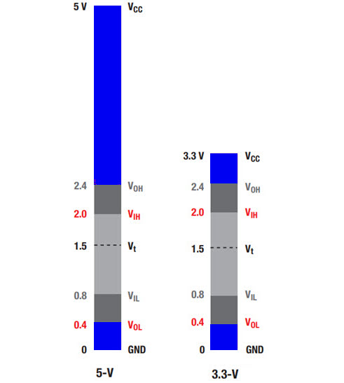
Logic Level Converter
.png)
Circuit Protection
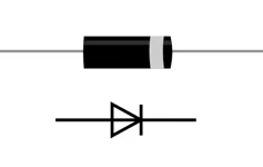
Diodes
.jpg)
PMOS / P-Channel MOSFET

Logic Level NMOS / N-Channel MOSFET
Voltage Measurement

Analog to Digital Conversion (ADC)

Variable output VDC
.png)
Turn On/Off Noisy DC Device
ADC Analog Input